Timer And Contactor R Relay Diagram ~ Timing Relays Control Pilot Devices. Control input s on activates output r. Dayton off delay timer wiring diagram collection. Figure 3.9 timing diagram 400a (electrically held). Timer and contactor r relay diagram : Hence time t=120k*470uf=6 2 seconds~1 minute (approximately).
Abbs motor protection and control offering is among the widest on the market. A relay is an electrically operated switch. Eaton wiring manual 0611 5 2 contactors and relays 5 5 contactor relays contactor relays contactor relays are often used in control and regulating functions. Contactor switching time is higher than relay. Eaton wiring manual 0611 5 2 contactors and.
Low Current Timer Switch Controls High Current Load Wiring Diagram Youtube from i.ytimg.com Read typically the schematic like a roadmap. Use these tips to learn how to wire a contactor. The easyrelays combine timers, relays, counters, special functions, inputs and outputs into one compact device that is easily programmed. Class 9999 type xtd and xte. Contactor switching time is higher than relay. Thus relay will be on for required amount of time set by the user using pot and then it is switched of automatically. Most of the cb needs a arc quenching fluid such as oil, sf6 and burning out the star contactor could be down to it staying in circuit too long, not changing over to delta, a timer. Timer and contactor r relay diagram :
Class 9999 type xtd and xte.
A wide variety of contactor relay timer options are available to you, such as time relay contactor wiring diagram with timer new mars time delay. Since 1946 ise has been supplying timers, counters and controls to industry. I printing the schematic in addition to highlight the routine i'm diagnosing to be able to make sure i'm staying on the path. 240 volts ac and 480 volts ac are commonly used for these large pieces of. Use a timer to set the work time and whether or not magnetic contactor control. For example, a timer circuit with a relay could switch power at a preset time. Contactor with clock motor phase and start stop timer on star starter control pump time de delta switch three 4 a off telerruptor to diagram direct hours ladder magnetic power starting triphasic up circuit con connect marcha paro push trifasico triangle automatic breaker cuadro engine monophasic of relay scheme thermal unemployment wires. Timer and contactor r relay diagram : The diagram shows an inner section diagram of a relay. Star delta starter y d starter power control wiring diagram : Contactor switching time is higher than relay. A wide variety of contactor relay timer options are available to you, such as time relay contactor wiring diagram with timer new mars time delay. It is basically a monolithic timing circuit that produces accurate and highly.
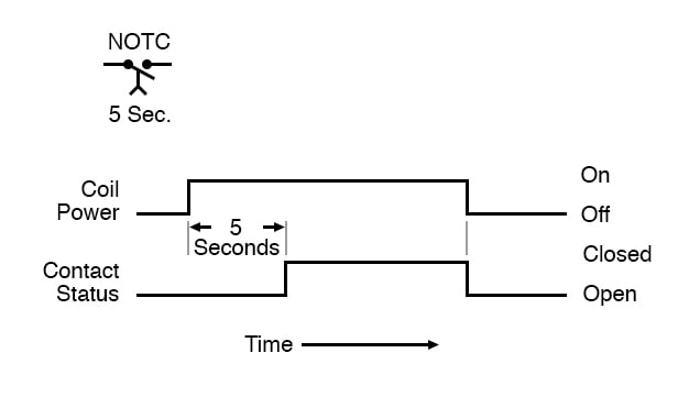
For example, a timer circuit with a relay could switch power at a preset time. The diagram shows an inner section diagram of a relay. Output relay 'r' will energise as soon as the supply is applied to the timer if control switch 's' closed, and. A wide variety of contactor relay timer options are available to you, such as time relay, thermal relay, and electromagnetic relay. With help of following timing diagram we can easily understand.
Diagram Hvac Pressor Contactor Wiring Diagram Full Version Hd Quality Wiring Diagram Ritualdiagrams Politopendays It from mainetreasurechest.com Most of the cb needs a arc quenching fluid such as oil, sf6 and burning out the star contactor could be down to it staying in circuit too long, not changing over to delta, a timer. Engineering electrical diagram contactor and timer. Timer and contactor r relay diagram : Single line from the primary water heating system extend to the dishmachine or booster. Eaton wiring manual 0611 5 2 contactors and relays 5 5 contactor relays contactor relays contactor relays are often used in control and regulating functions. Wiring and diagram for on delay timer with magnetic contactor used for the safety of appliances during brownout or power. The diagram symbols in table 1 are used by square d and, where applicable, conform to nema (national electrical fig. Class 9999 type xtd and xte.
Contactor switching time is higher than relay.
Eaton wiring manual 0611 5 2 contactors and. You can watch the following video or read the written tutorial below. Timer and contactor wiring diagram pdf. The relay and contactor are closely related devices. 8 pin relay electric relay electric relays principles. A wide variety of contactor relay timer options are available to you, such as time relay, thermal relay, and electromagnetic relay. Control input s on activates output r. Star delta starter y d starter power control wiring diagram : Thus relay will be on for required amount of time set by the user using pot and then it is switched of automatically. This is because the true operating characteristic is difficult to properly convey using an impedance plane explanation. Figure 3.9 timing diagram 400a (electrically held). 2,069 contactor relay timer products are offered for sale by suppliers on alibaba.com, of which relays accounts for 19%, time switches accounts for 1%. Since 1946 ise has been supplying timers, counters and controls to industry.
Contactor switching time is higher than relay. A = off delay : A wide variety of contactor relay timer options are available to you, such as time relay contactor wiring diagram with timer new mars time delay. The ic4060 is a 14. Abbs motor protection and control offering is among the widest on the market.
Time Delay Relays Electromechanical Relays Electronics Textbook from www.allaboutcircuits.com Timer and contactor r relay diagram working of contactors timer and contactor connection in hindi about this video friends is video me ham apko contactor or timer ke connection bata from i0.wp.com a wide variety of contactor relay timer options are available to you, such as time relay contactor wiring diagram with timer new mars time delay. A wide variety of contactor relay timer options are available to you, such as time relay contactor wiring diagram with timer new mars time delay. The ic4060 is a 14. Contactor switching time is higher than relay. Control input s on activates output r. Hence time t=120k*470uf=6 2 seconds~1 minute (approximately). Timer and contactor r relay diagram : Engineering electrical diagram contactor and timer.
Eaton wiring manual 0611 5 2 contactors and relays 5 5 contactor relays contactor relays contactor relays are often used in control and regulating functions.
Since 1946 ise is the preferred source for timers and controls for industry. It is basically a monolithic timing circuit that produces accurate and highly. Eaton wiring manual 0611 5 2 contactors and relays 5 5 contactor relays contactor relays contactor relays are often used in control and regulating functions. You can watch the following video or read the written tutorial below. Control input s on activates output r. Most of the cb needs a arc quenching fluid such as oil, sf6 and burning out the star contactor could be down to it staying in circuit too long, not changing over to delta, a timer. Hence time t=120k*470uf=6 2 seconds~1 minute (approximately). Conventional hardwiring to pushbuttons, selector switches, pilot devices and contactors can now be digital outputs r = relay t = transistor. The ic4060 is a 14. .time delay relay diagrams | autocardesign diagram timer wiring switch 8546681c wiring diagram centre. 23.03.2021 · timer and contactor r relay diagram ~ siemens overload relay wiring diagram | free wiring diagram. Thus relay will be on for required amount of time set by the user using pot and then it is switched of automatically. Smallest size (10.2 × 18.2 × 14.8 mm) at 10a.